On Sunday 20th October, I set off to Youlbury with my friends Graham, Theresa and young Sebastian to launch VAYU-1 for the Scout JOTA day. In the preceeding week, I’d checked the weather forecast and it consistently said that it would be cloudy with rain spells. When the time came, I took a gamble that there would be enough clear sky to launch. We made good time and arrived shortly after 12:00 despite a lengthy stop at services for a late brekkie.
We were very warmly greeted by Steve Hunter (M0SXH) and Richard who quickly introduced us to everyone else. Whilst we waited for Dave Akerman (M6RPI) and my friend Charlie Robson to arrive, we had a cuppa and a chat. I was keeping an eye on the weather and it was certainly clear enough to launch at that point. I begun to prepare and hung VAYU-1 on a window catch for a quick test.
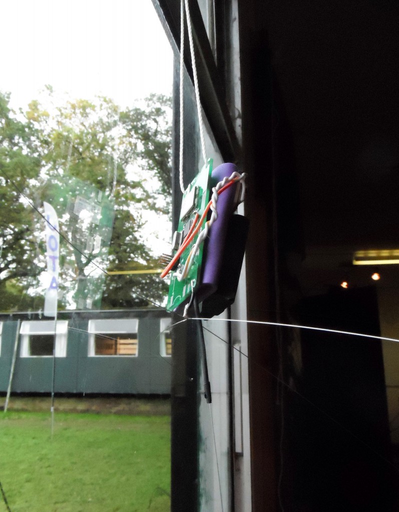
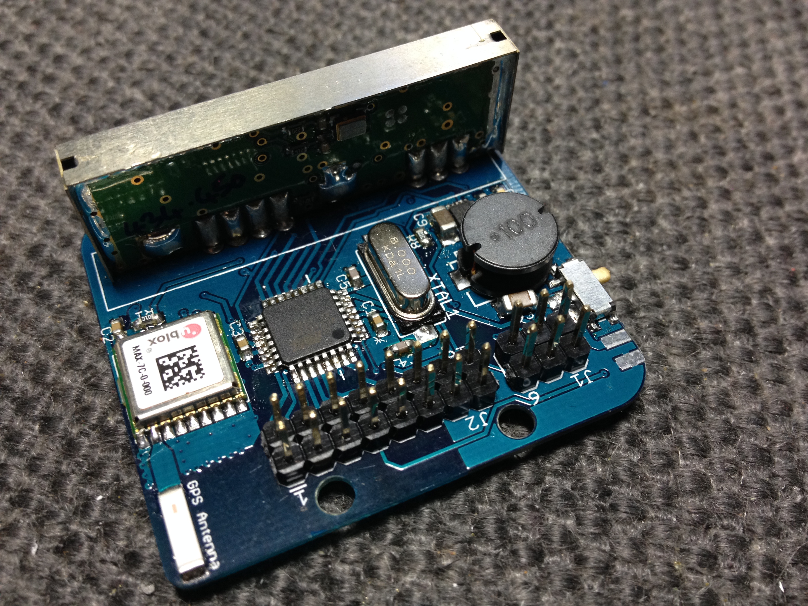
VAYU-1 payload hangs in the Window for a quick test.
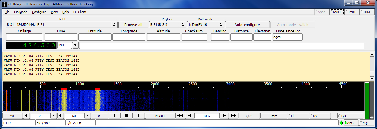
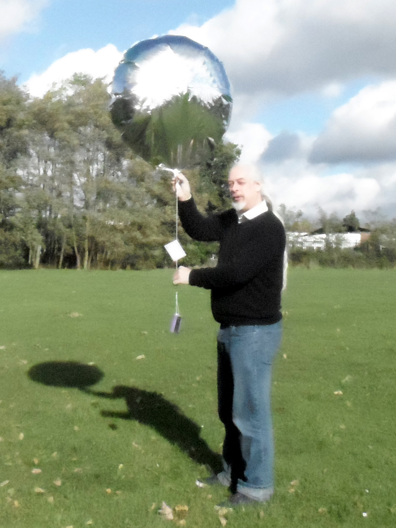
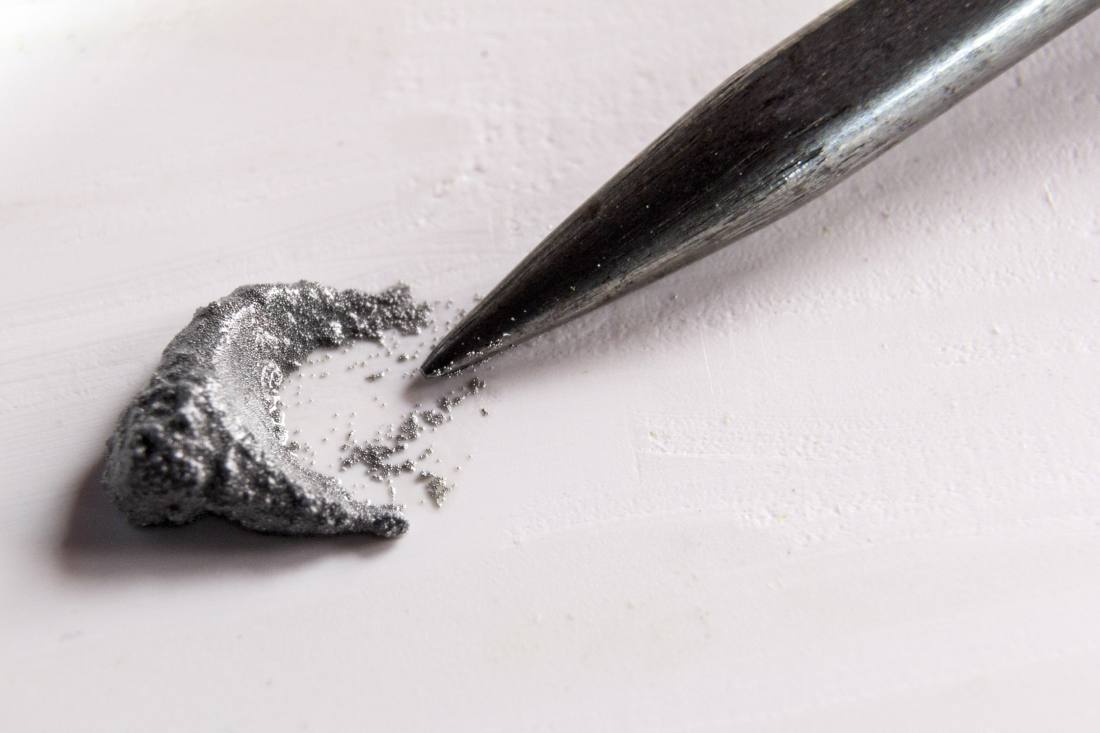
I showed Steve and Richard how to receive the telemetry on their radio kit and indicated what appears on SpaceNear. Shortly after this, Charlie arrived followed by Dave a little while later. Now everyone had arrived, I begun to prepare for the flight in earnest. Dave and Charlie assisted me with inflating the foil balloon and Dave showed me how to use ballast to measure the lift. This involved suspending a weight of known quantity under the balloon and then measuring how much lighter the weight was when the balloon was allowed to lift it. I used an open ended container filled with rice. As we filled the balloon to get the right lift, we threw in some other weights I’d made from small amounts of solder.
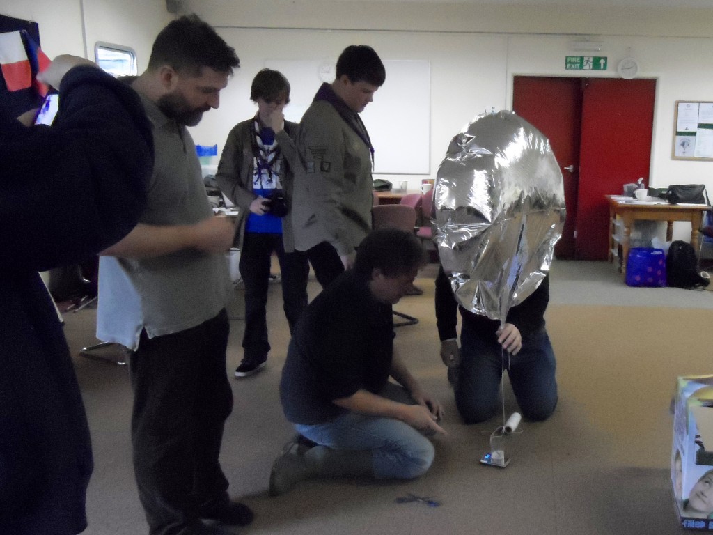
Getting the lift right
During this time, I was explaining to the assembled folk what High Altitude Ballooning was all about and what I was trying to achieve with VAYU-1. I explained that the reason I chose a small foil ‘Pico’ balloon for my first launch is so that I could go through the motions and get some experience without it costing a fortune. As in most endeavors, there is a steep learning curve and I wanted to make sure I had a good idea of the procedures and possible pitfalls involved in launching a balloon. I really appreciated having Dave Akerman assisting, a veteran of many launches.
Dave had brought his mobile tracking kit as well as the now famous Babbage the bear. In an interlude, Dave showed us how he had managed to get a Raspberry Pi board, batteries and a camera inside Babbage for his epic jump.
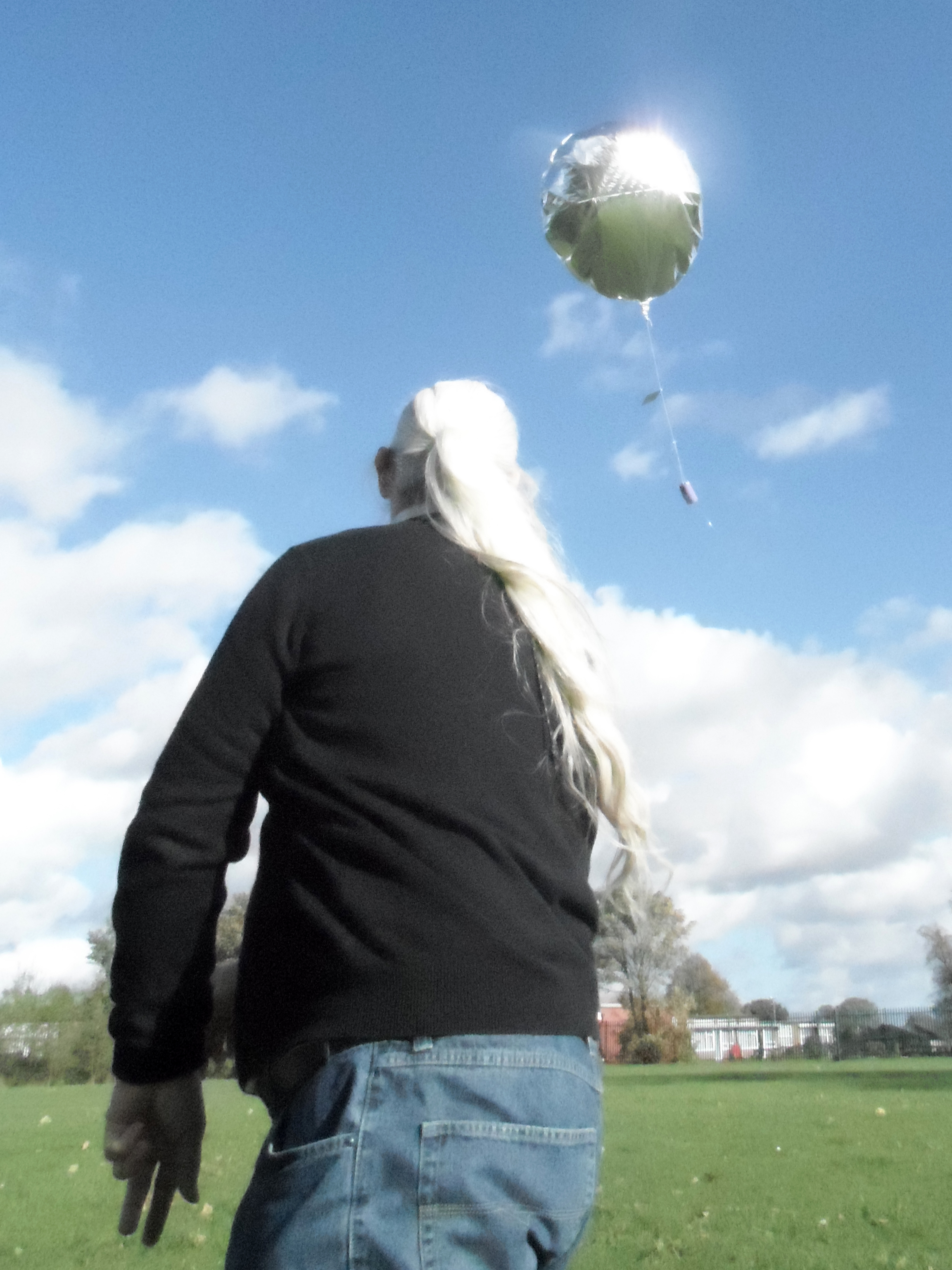
Having set up the balloon and VAYU-1 payload, it was time to launch. Sadly, the weather had turned a little sour. However, we went ahead. Steve went and grabbed some more interested Scouts whilst I led Dave, Richard and everyone else out to a field opposite the Scout complex. After a quick chat with Dave, I decided to launch from the adjoining field where the Scouts could watch from the fence. Dave followed me all the time and streamed video to the BATC website.
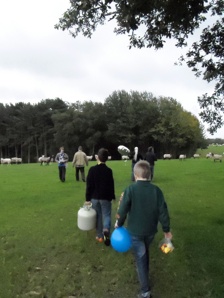
Procession to the launch
Trying not to disturb the sheep, I positioned myself as far down the field as possible. This was to ensure the balloon didn’t hit either the power lines running across the field or the line of trees making up the border. I watched Dave for my que to launch since he was in a better position to feel the wind than I was. He gave the word and I released my first flight with a push. Worryingly, the balloon didn’t climb very fast and we were all shouting ‘Up! up!’ at it in a feeble attempt to get it higher in the air. Luckily, it did start to climb faster and we watched it as it gracefully floated over the tree line.
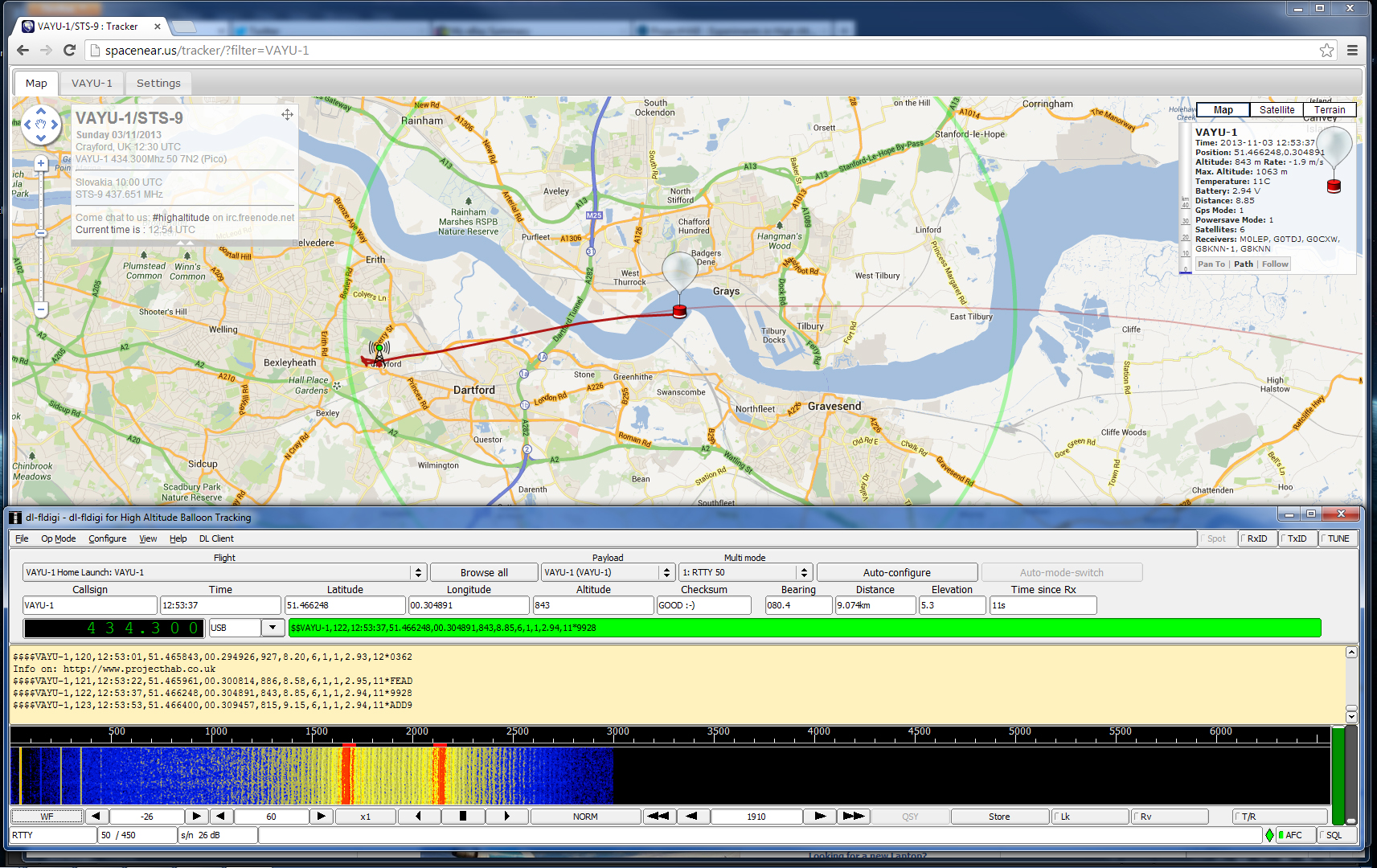
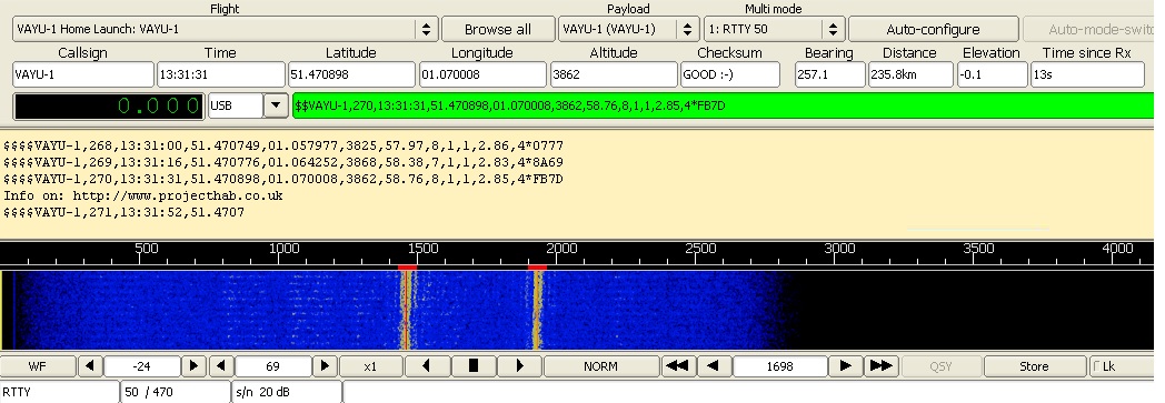
We walked back to the complex and I realised that I hadn’t done any tests with small balloons, which I had planned to do. Note to self: Don’t get so excited! Once back in the complex, I explained to the Scouts in the adjoining tent how the tracking would be done. They had SpaceNear projected on a screen for everyone to see.
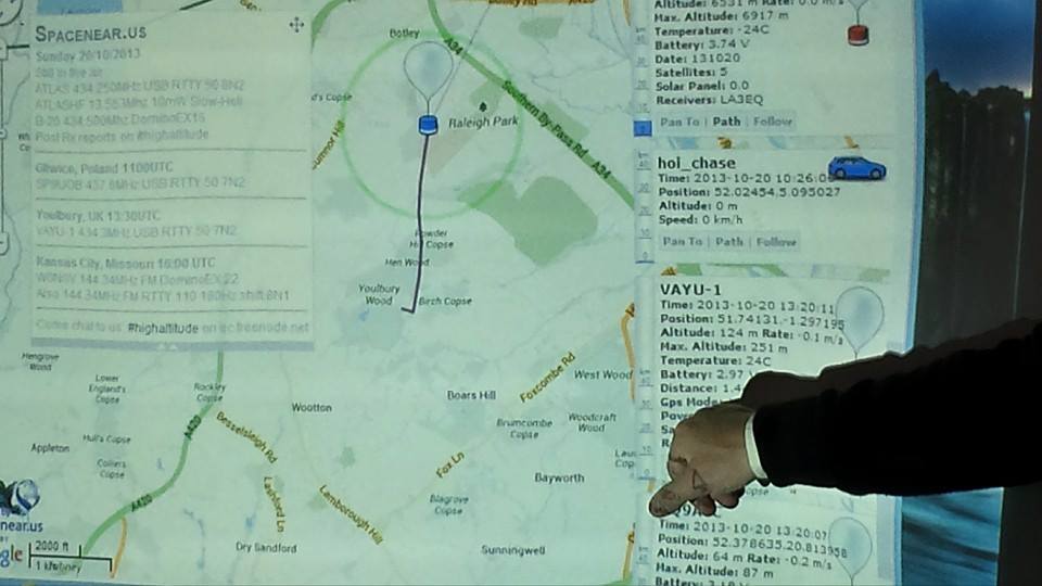
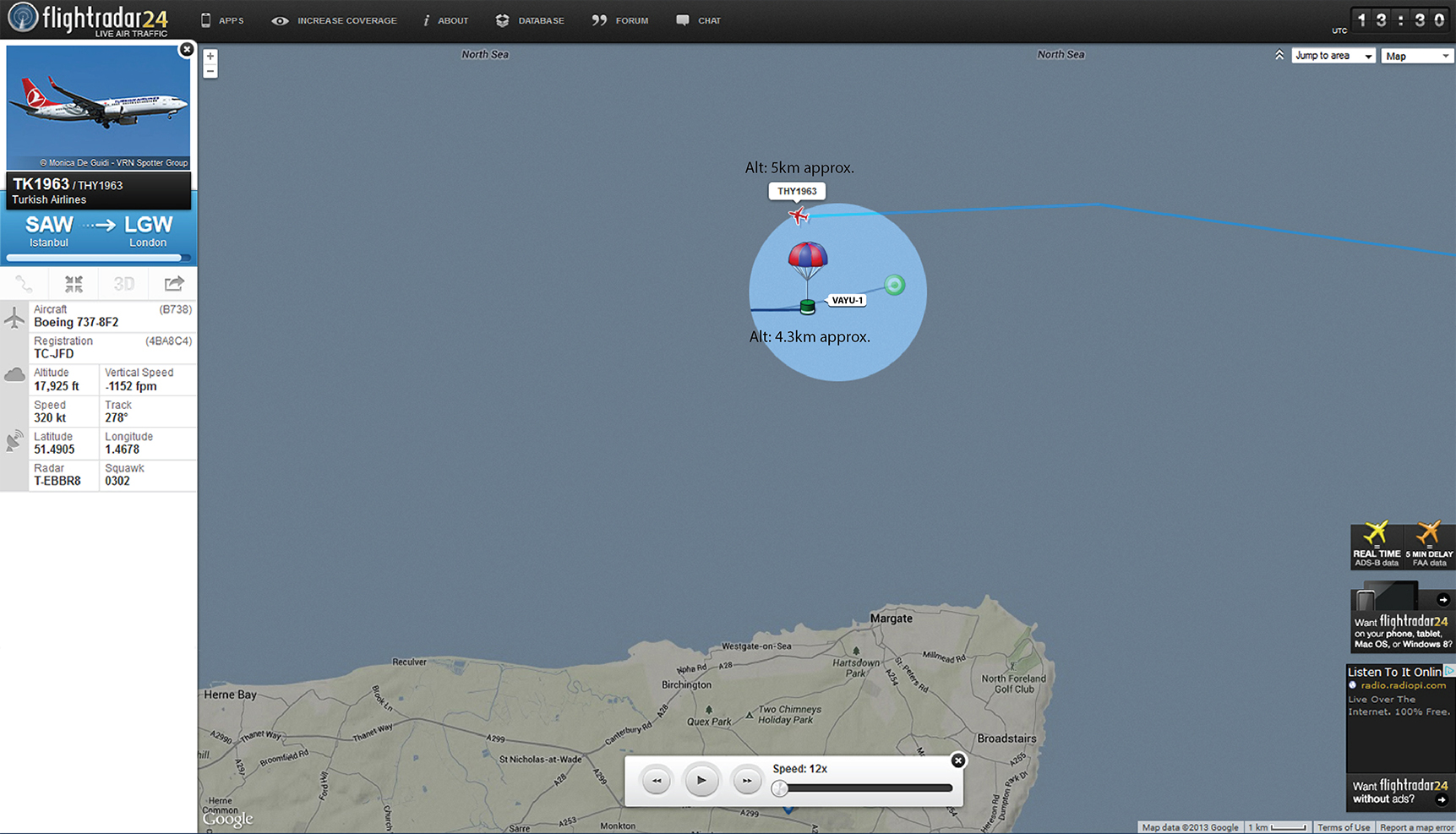
VAYU-1 on SpaceNear Tracker page being projected onto a screen.
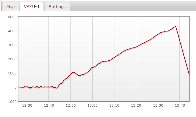
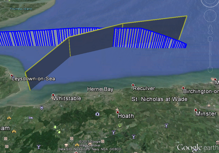
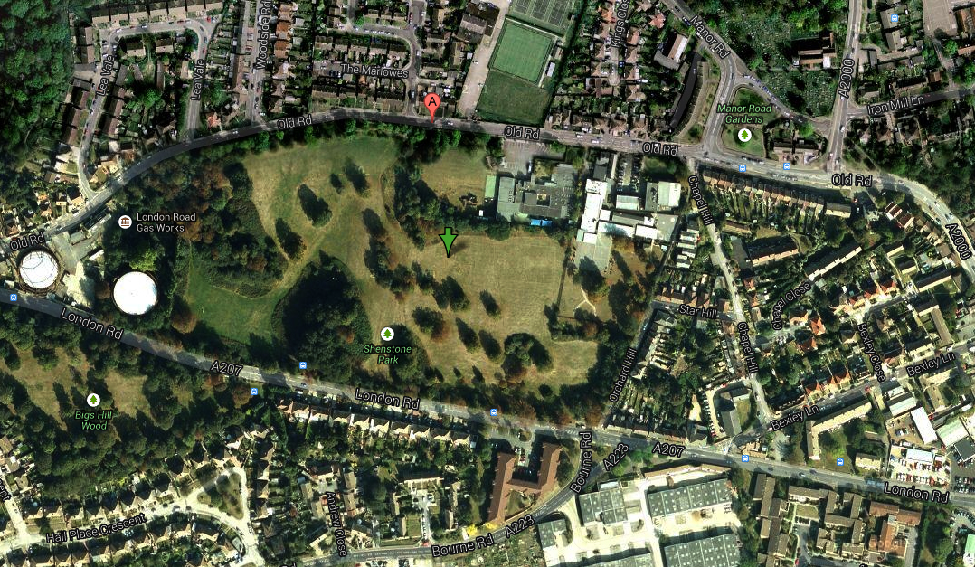
As we made our way back to the hut to decide which way was best to chase VAYU-1, we had no idea of the difficulty it was having staying aloft. The rain had started and was forcing VAYU-1 back down. We realised what was happening when we tried to receive the telemetry back at the hut. There was no signal to be found. It was deduced that VAYU-1 had landed about one and a half kilometers away. A group of us assembled to see if we could retrieve the payload. Richard kindly gave us directions for the best way to exit the complex. Graham led the way and we set off to find VAYU-1.
By this time, the heavens had opened and I was very unsurprised that VAYU-1 had come down. The weight of the water on the balloon must have been quite high. We arrived in the vicinity of the landing where Dave reported a good signal. Sebastian and I set off in the rain to see if we could locate the downed balloon. We searched around for quite a while before I realised I’d got a helpful text message from Chris Stubbs detailing where VAYU-1 was likely to be. This was a great help and pointed us in the right direction. On the way, Steve phoned to tell us he and Richard had joined us to help in the search. I explained where Graham and Dave were parked and they headed for a rendezvous.
Sebastian and I were drenched by this time but we didn’t want to give up. I was very pleased hen Sebastian exclaimed ‘Is that it?’. I looked and indeed, Sebastian had spotted the balloon up in a Hawthorn bush. It was too high up to reach without aid so we tried to recover the payload with a flagpole, loaned from the field adjoining us. This proved ineffective but as luck would have it, Steve had let us bring a telescopic pole and a set of loppers from the Scout complex. Sebastian and I went back to the cars to collect them to find Steve and Richard pulling up in their car.
After retrieving the equipment from the car, Steve and Richard elected to join us in recovering the payload. Dave had reported loosing the signal from his car so I was a little concerned that I’d damaged the payload by trying to retrieve it with the flag pole. We got back to the landing site within a few minutes and Sebastian and I together got the payload out of the Hawthorn successfully. After Steve had taken a few pictures on his phone for posterity, I identified that I’d broken the power switch off of the regulator board. This had obviously cut the power but the payload was otherwise undamaged.
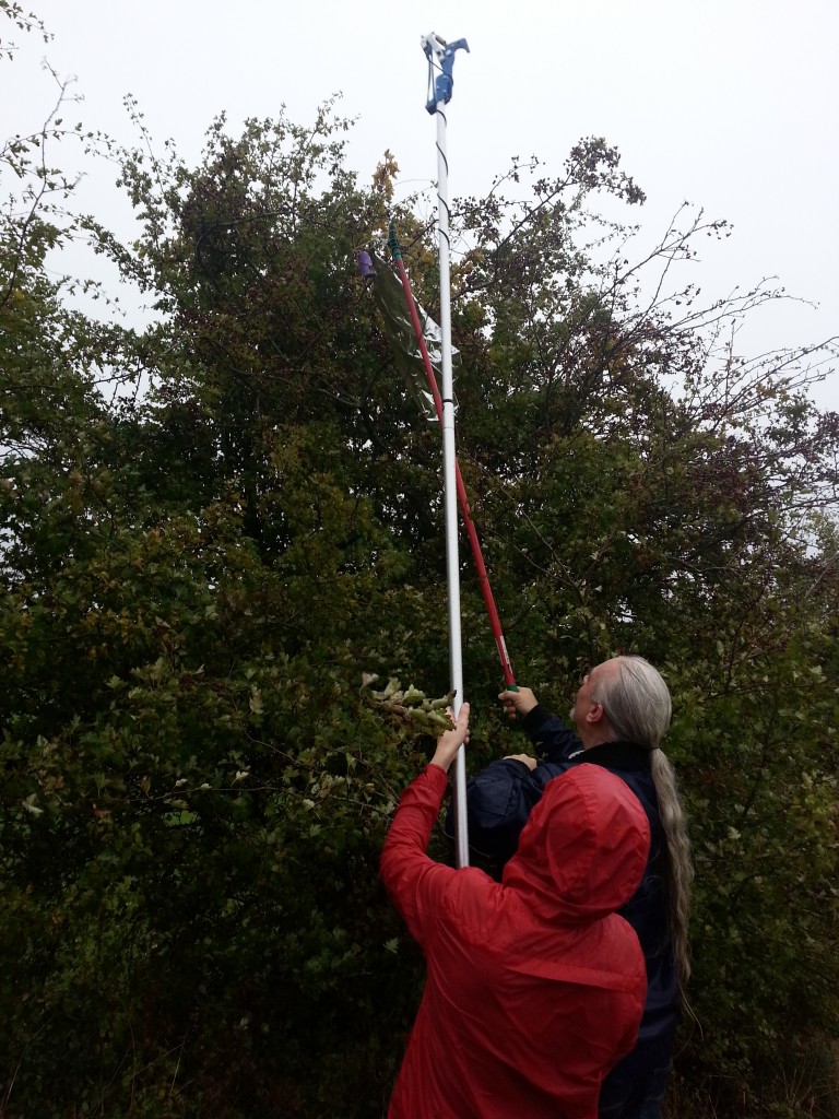
Steve & Sebastian recovering VAYU-1 – Photo Steve Hunter
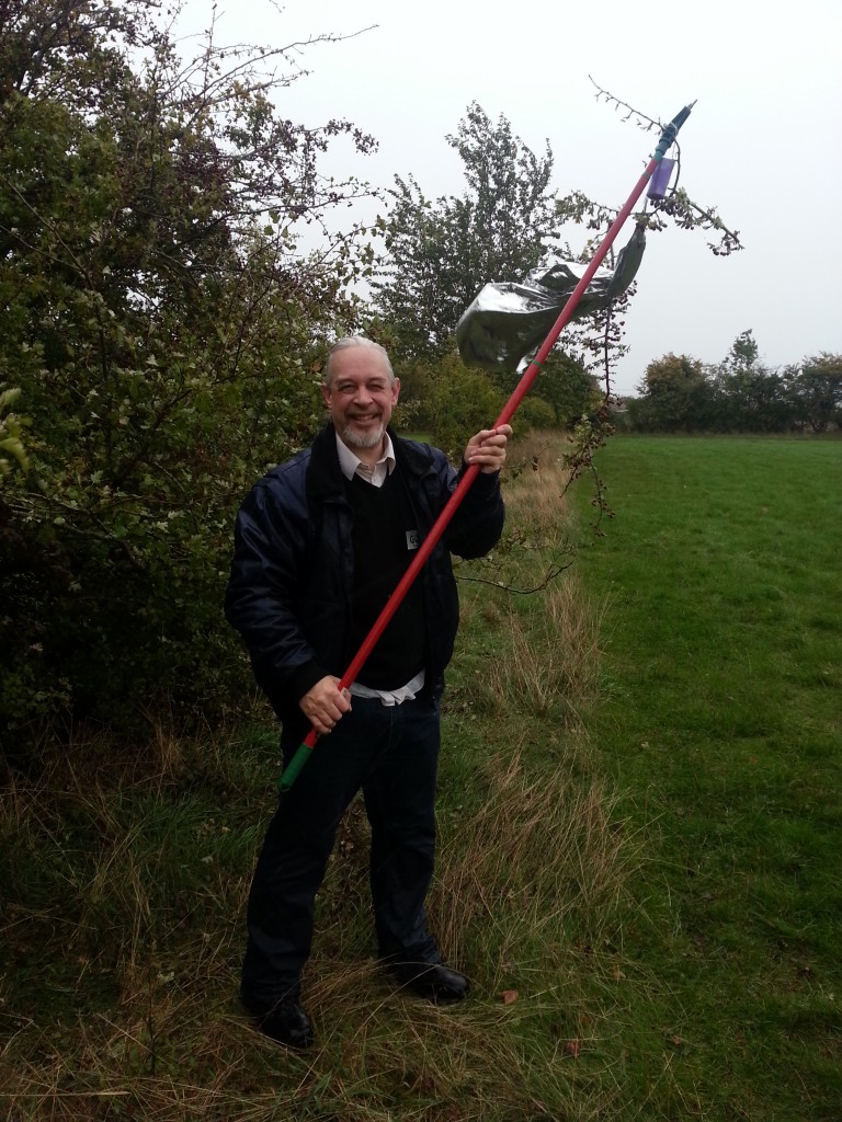
Recovery successful! – Photo Steve Hunter
After removing the bits of Hawthorn from the deflated balloon and VAYU-1, Sebastian carried it back to the car. Despite the short flight and the rain, we were all smiling.
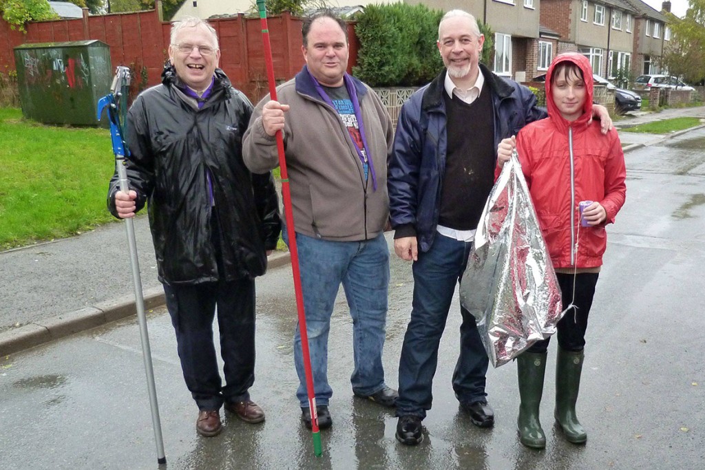
Recovery Team: Richard, Steve, Myself and Sebastian – Photo Dave Akerman
After I had separated the balloon from the payload, we all said our goodbyes. Despite a very quick flight and an extremely wet recovery, it had been lots of fun. I had been able to demonstrate a launch and the preparation beforehand and had managed a successful recovery. VAYU-1 will fly again soon.
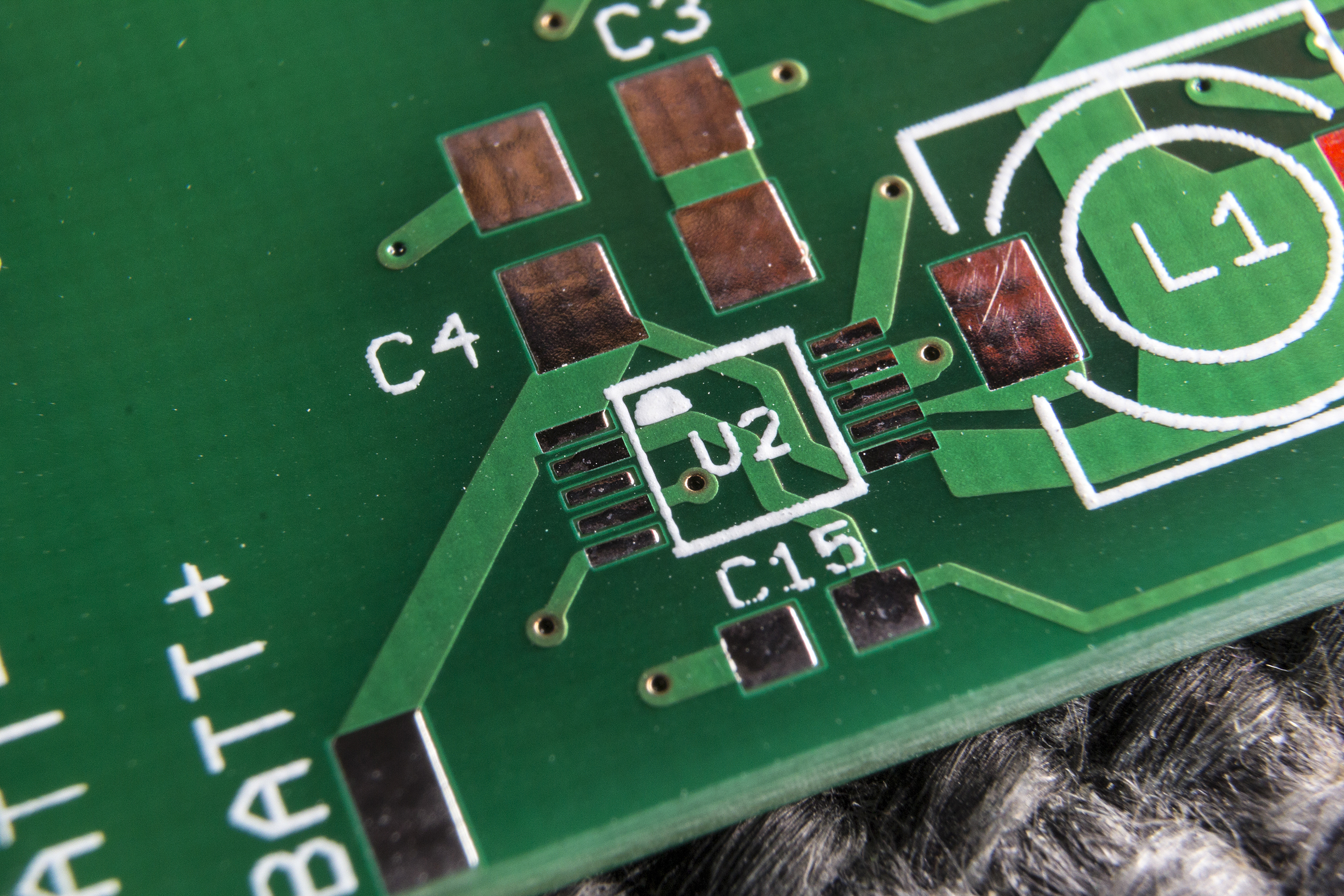
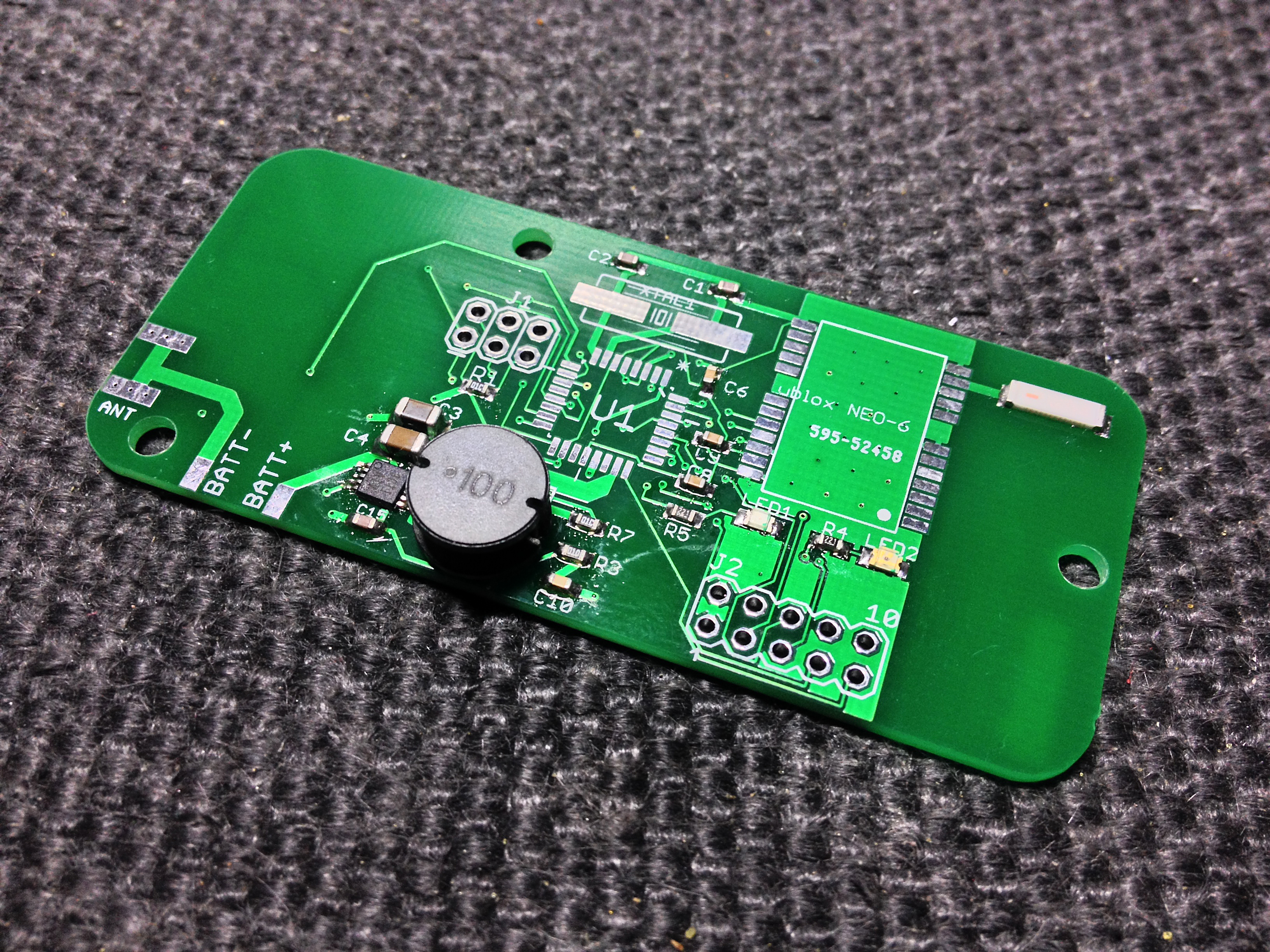
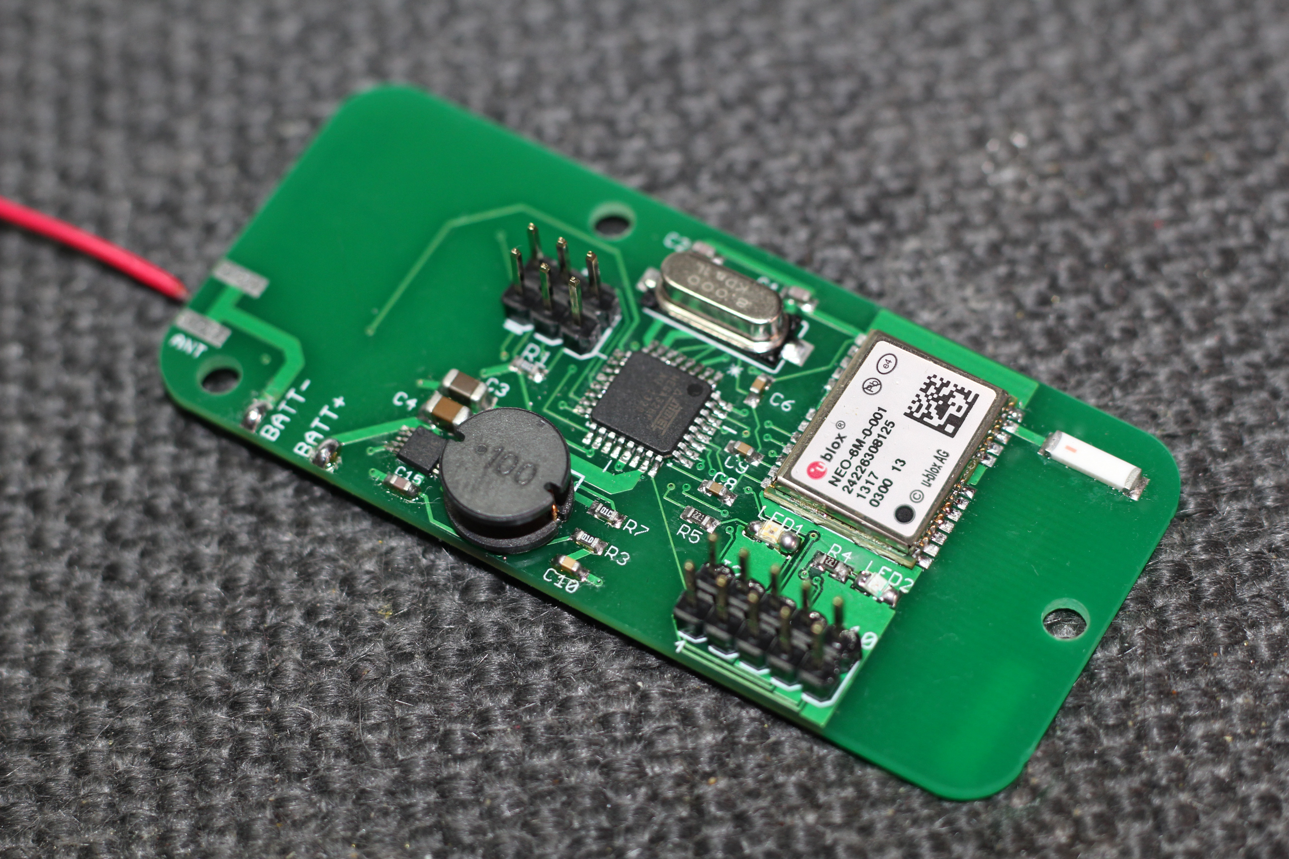
I had lots of assistance in this endeavor. Firstly from Chris Stubbs, whose circuit and PCB VAYU-1 is based on. I had loads of help from all the guys involved in UKHAS which I appreciate immensely. A big thanks to Dave Akerman and Julie for coming along to assist. I was made extremely welcome by Steve, Richard and all the Scouts and staff at Youlbury. But the biggest thanks must go to my friends Graham, Theresa and Sebastian for getting me there and especially Sebastian for spotting the balloon!
Despite the short flight, I learned a lot on my first launch. The knowledge I gained will be invaluable for future launches. I also made some great new friends too!