During the building of VAYU-1 and VAYU v1.01, I developed a technique for soldering the very small SMD parts including the TPS16016 Boost Regulator chip. This device is a mere 2.5mm across and the pins are minute. Try as I might, I can’t find a syringe that will deliver a thin enough line of solder paste and I’m not in a position to obtain a solder stencil. So, I had to try and find a way that I could easily solder SMD parts myself. I am no stranger to crafts and have some bits and pieces lying around. I decided to try and apply the solder manually, with a pointed implement. I found this tool that came from a scalpel set I had many years ago.

Pointed Implement
I use an old SIM card carrier as a palette and put a small blob of solder paste on it from the dispensing syringe.
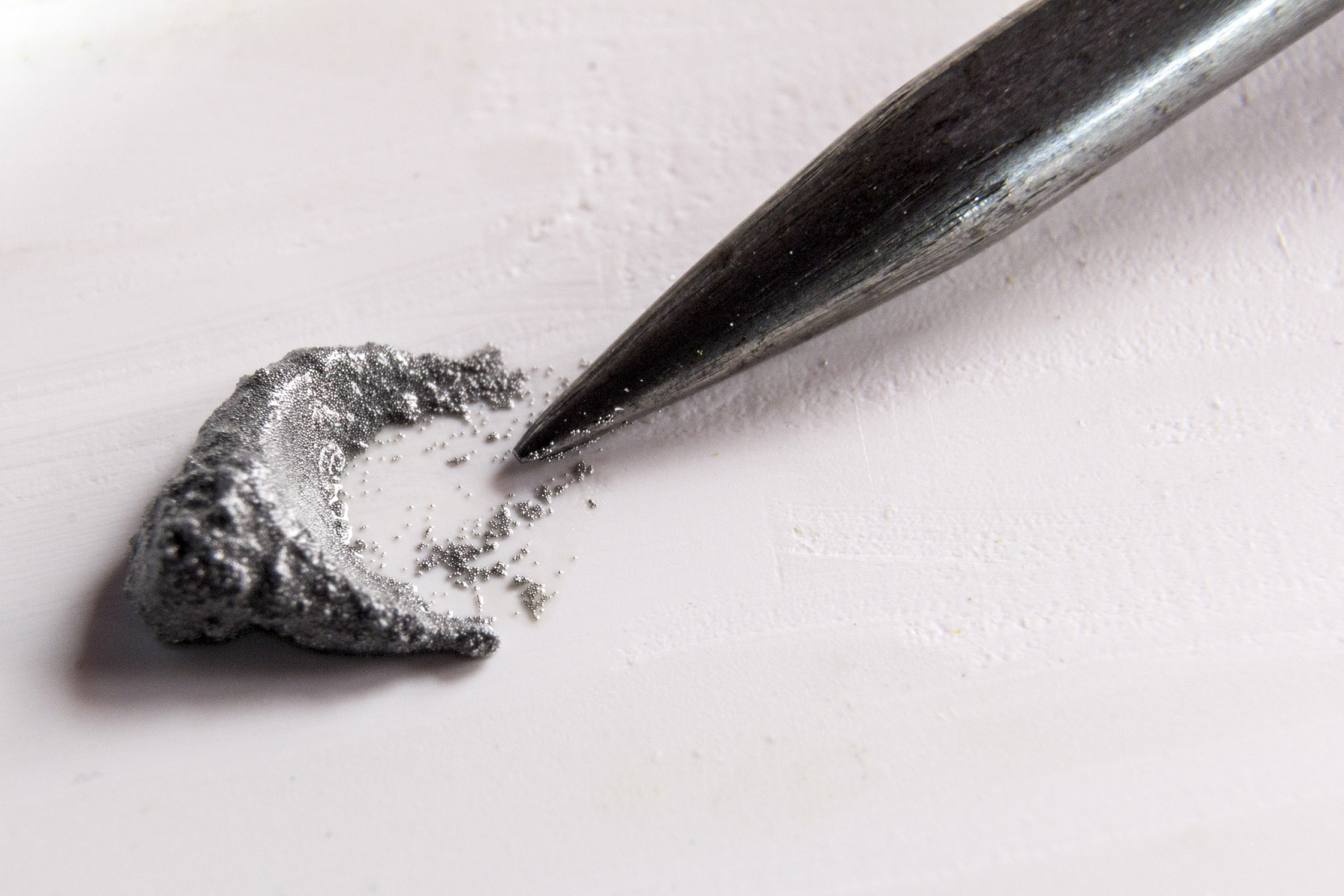
Solder paste
In this instance, this is much too much for a single 8-pin SMD chip. The pads on the board are cleaned if required to make them ready to receive the solder paste.
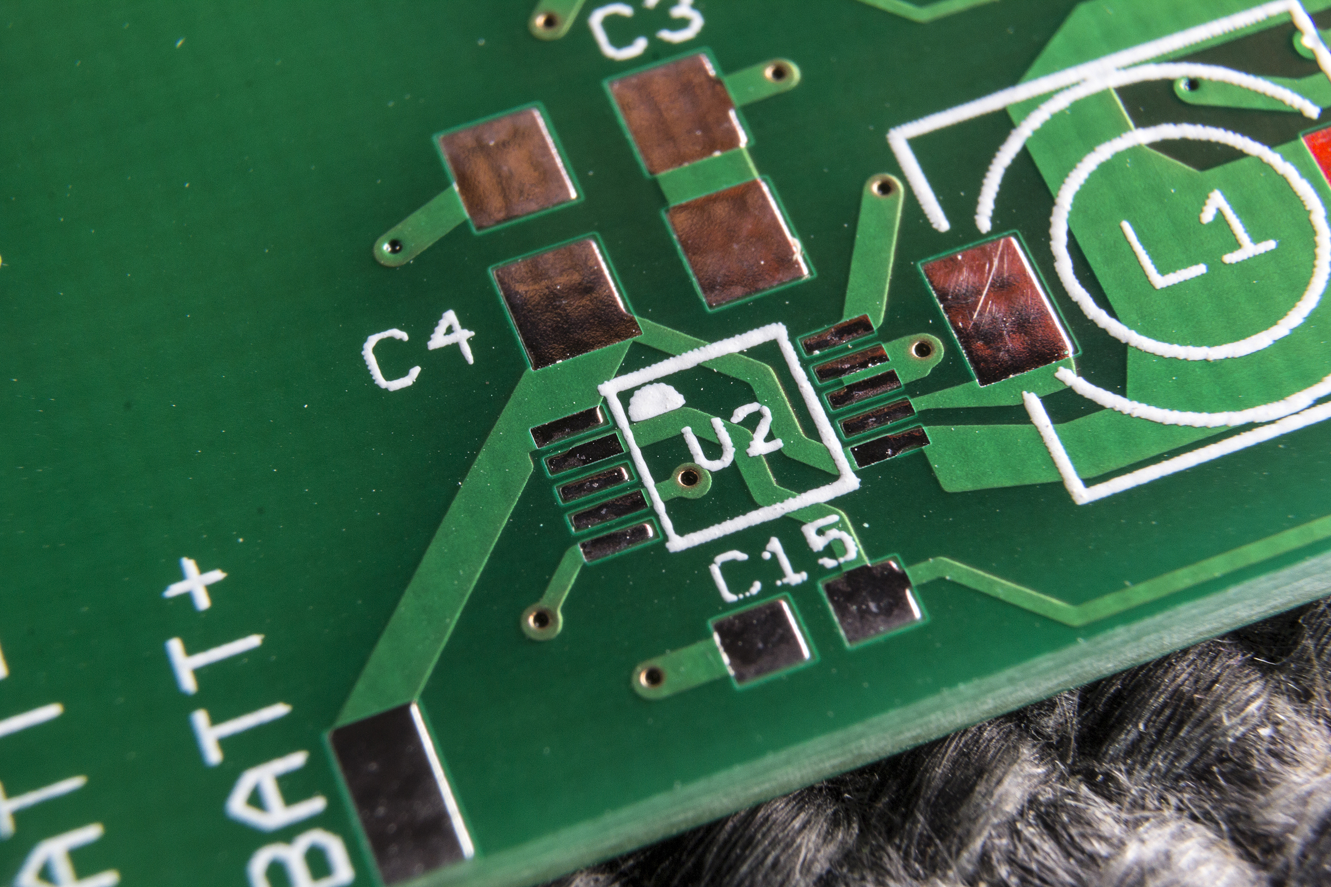
Clean pads ready to accept TPS16016 chip
Using a jewelers glass, I pick up a minute amount of solder paste on the very point of the ‘pointed implement’ and touch it on the pads, I then roll the implement so that the solder is deposited on the pads. There is a knack to this so you might like to practice on a few old boards first. Once you have enough solder paste along the contacts, you can tidy the line up with the implement by carefully nudging the paste around. You will end up with something looking like this:
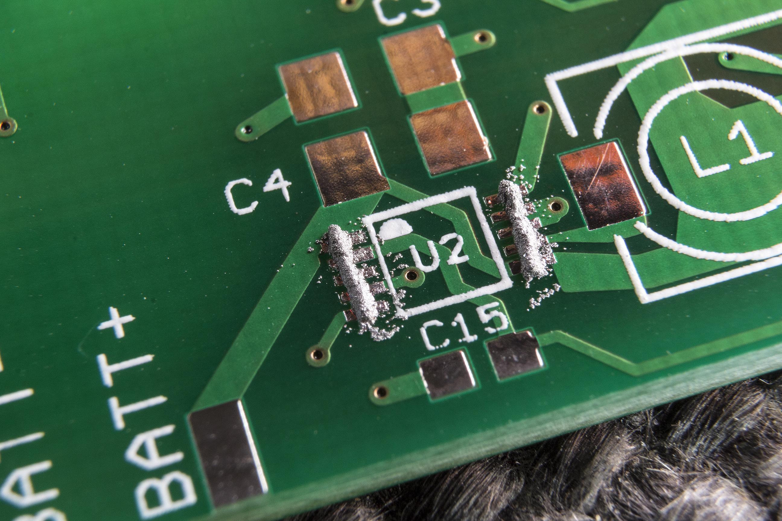
Solder paste applied to the pads
In this instance, I have gone a little over the top. The first one I did had less solder on it and worked fine. This one caused a small problem, more of that later. I was up against failing light so I rushed, something I should have known better than to do.
Once the solder is in place, you can carefully place the component in the correct orientation on the pads. I bought a set of anti-static tweezers on eBay for this purpose. After placement, you can nudge the component so that it is in exactly the right place.
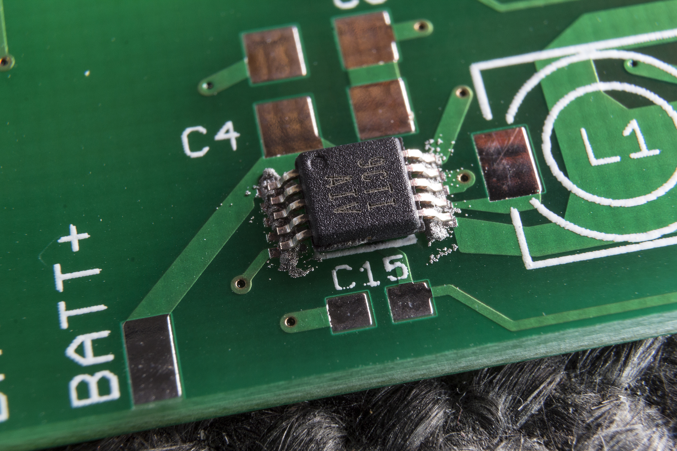
Component placed
I should have realised there was too much solder paste by this point but like I said, I was in a rush. This will still demonstrate the technique though. The next step is to use a hot-air soldering station to apply hot air on the solder paste. I set mine to 300 Deg and it seems to work fine. You can see the solder paste go shiny once melted and the surface tension should draw the solder to the contacts.
As I have said, there was too much solder in this instance and that led to solder bridges across several contacts, here indicated by the red circles. There were two bridges on the other side of the chip too.
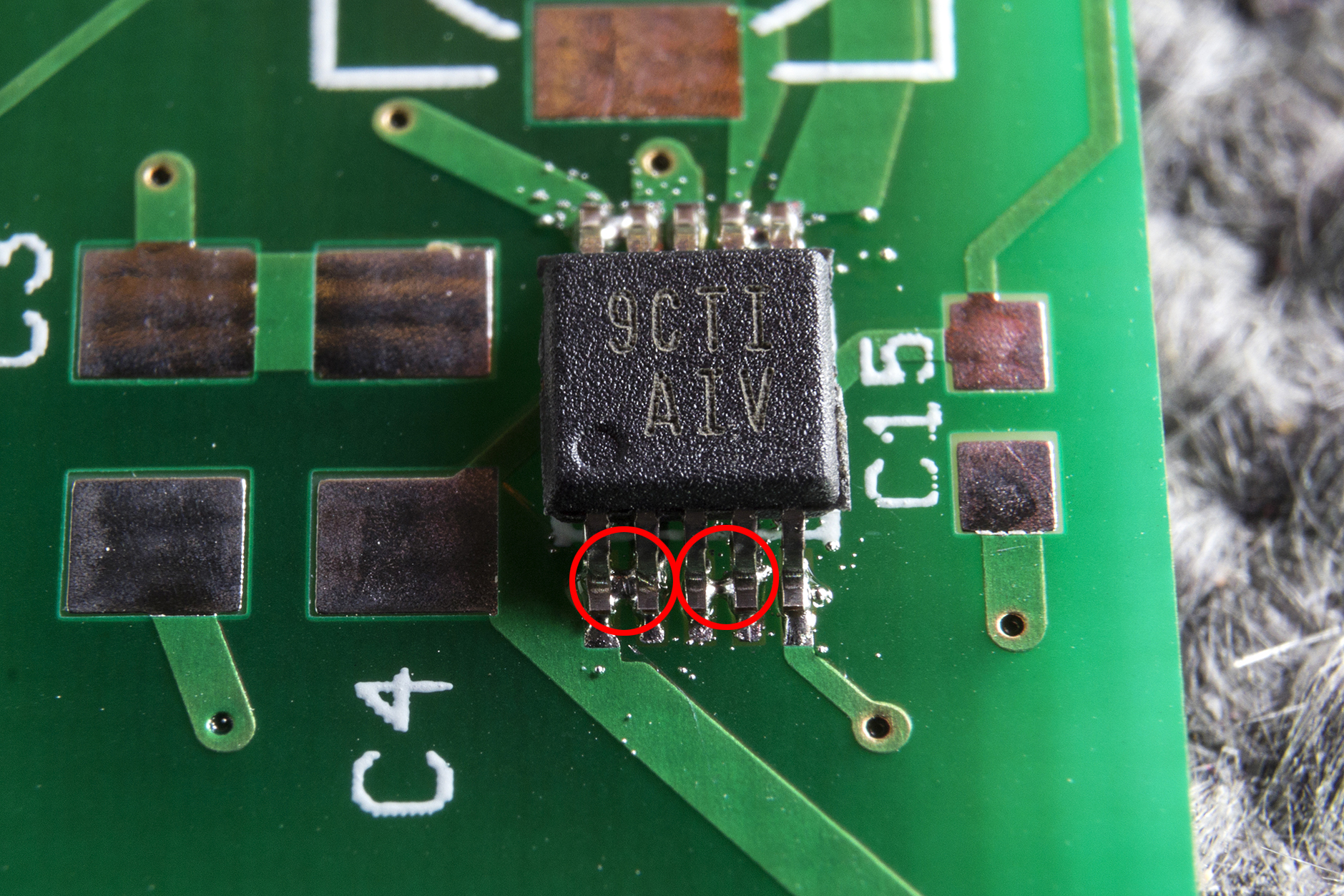
Solder Bridges
My answer to this is to use a standard fine-tipped soldering iron and a dress making pin. I place the pin in the gap between the legs of the chip, heat them up and draw the pin out. This normally brings the excess solder out. Again, I’ll point out that this shouldn’t be necessary except for my impatience in getting the images together.
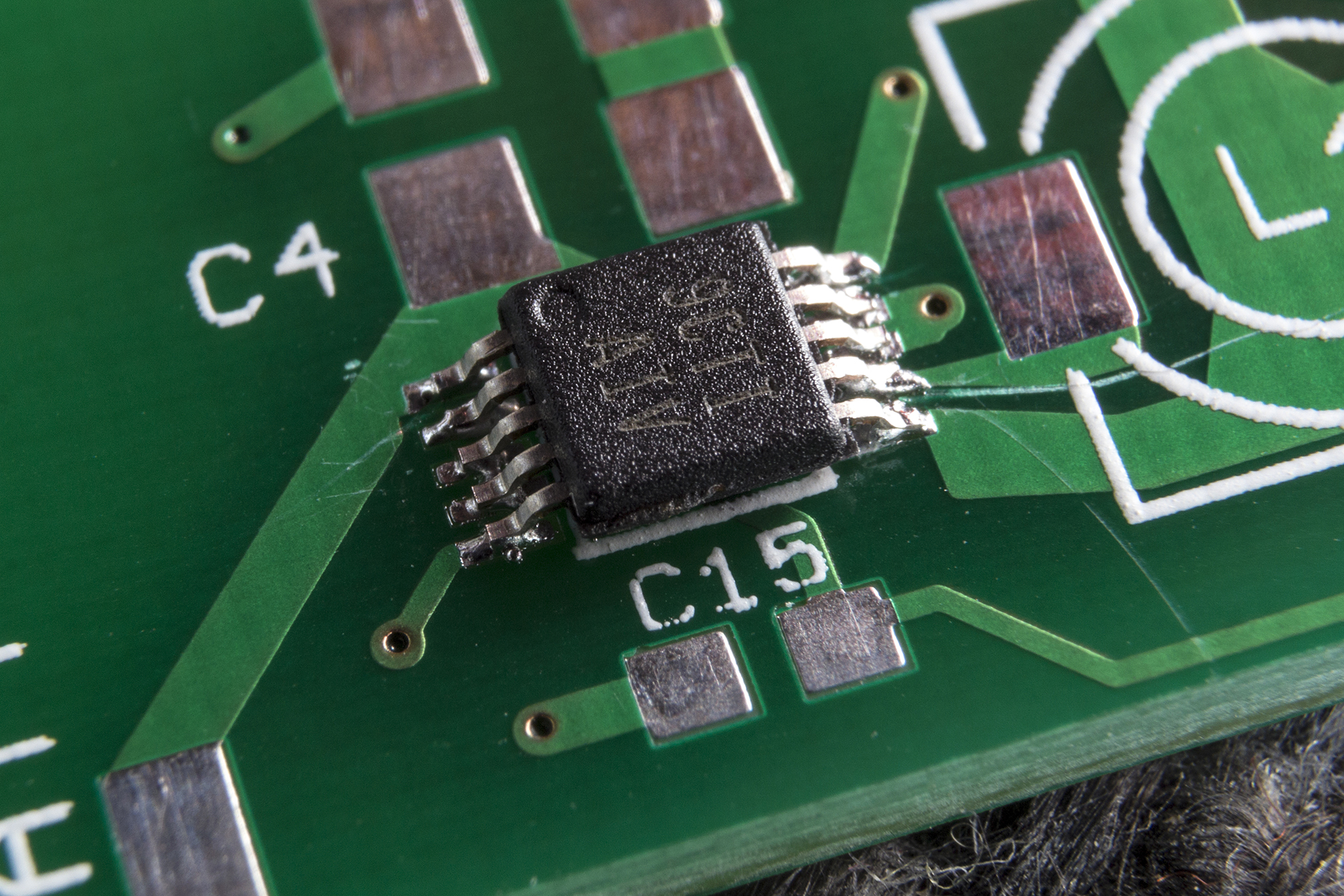
The Finished Soldering
I have slightly scratched the PCB with the pin by drawing too hard between the legs of the component but it won’t affect operation. I will be a lot more careful in the future. If I had of used half the amount of solder paste, I would have obtained perfect joints, as I did on the VAYU v1.01 prototype board. I hope others can learn from my mistake.
You must be logged in to post a comment.