Tuesday 19th saw delivery of the VAYU-NTX v1.03 prototype PCBs from Hackvana. I am really pleased with the consistency of quality and finish on their PCBs. I chose a blue colour this time and I really like it. It’s not a traditional blue but leans towards green and I like the effect. Well done Hackvana once again.
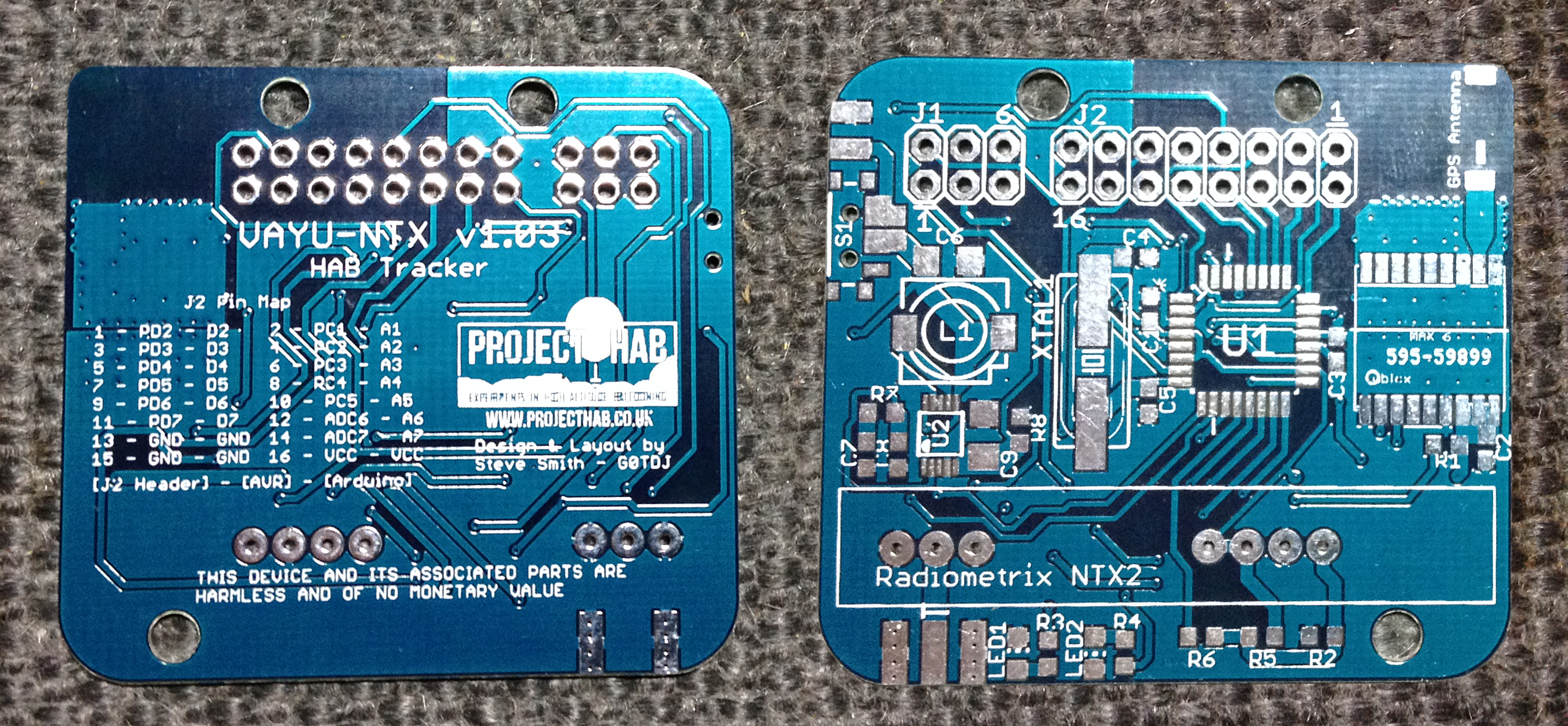
VAYU-NTX v1.03 PCB Top & Bottom sides
I am also very pleased with how the silk screen print shows up. It is very easy to read.
During that afternoon, I assembled the first board. I used the same techniques I describe in a previous post. It takes quite a while so patience is of the essence, but I would rather take the time to get it right than ruin a board.
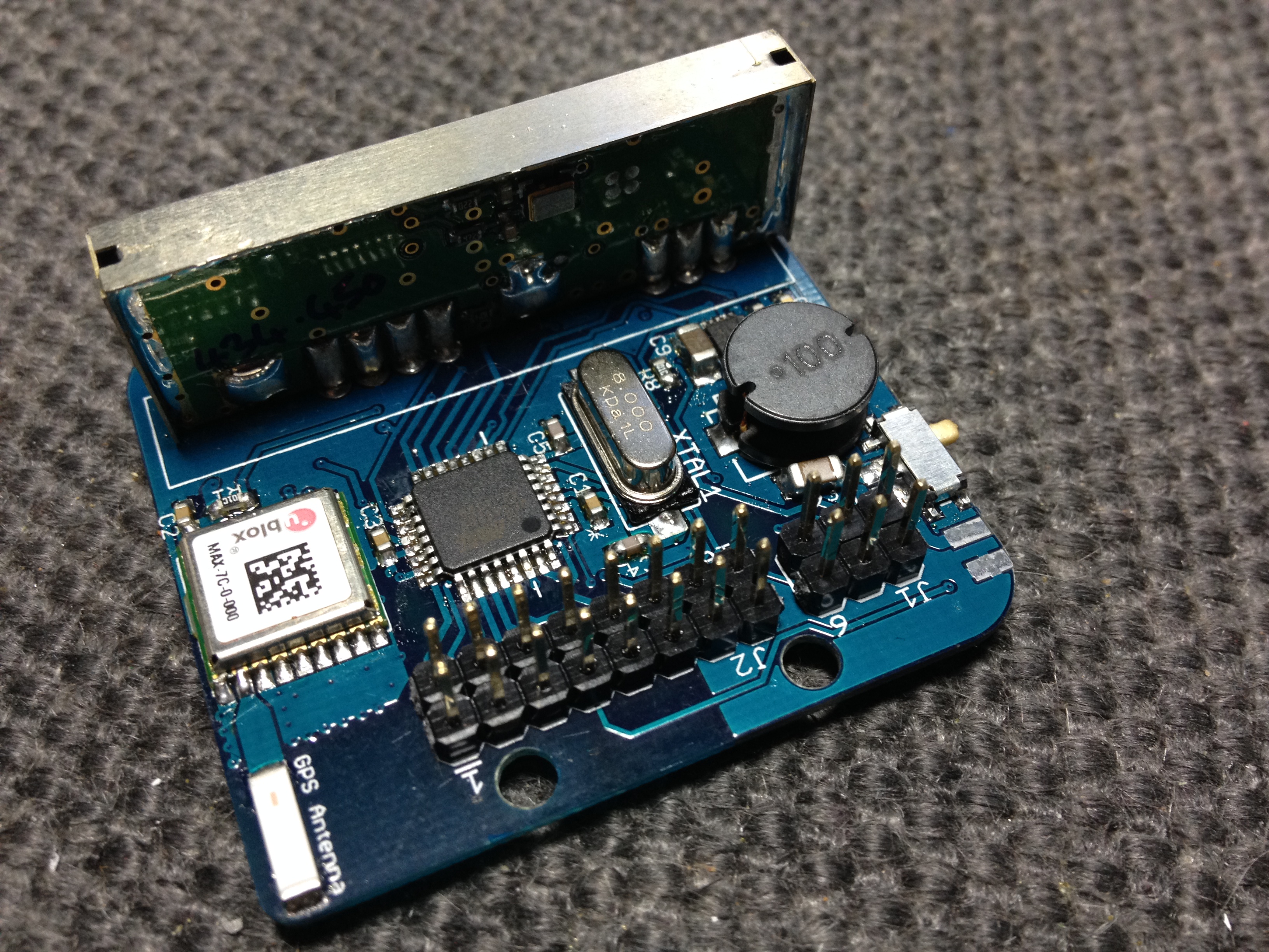
VAYU-NTX v1.03 PCB fully Assembled
I did have a little difficulty with the 100µH coil. The base was a little too large for the footprint I had accounted for on this board and I had to break a small piece of ferrite off to get it to fit properly. It doesn’t seem to affect the operation but I will source an alternative component for the final version. You can see in the above image, the capacitor behind the coil is at an angle. I eventually had to de-solder the coil altogether and re-seat it to get it to connect properly. Apart from that minor setback, the board went together relatively easy.
Later that day, I looked into trying some test code and after uploading the standard Arduino bootloader, I got one of the on board LEDs to blink.

VAYU-NTX v1.03 PCB Blinking test
So having ascertained that the ATMEGA329P was operational, I looked into running some RTTY code. Anthony Stirk had alerted me to some posts he had written on how to get this to work, namely his ‘Getting started with the NTX2b and the Arduino’ Part 1 and part 2. I realised very quickly that I had made a bit of a blunder on the VAYU-NTX circuit. I had connected the NTX2b’s TXD pin to a digital pin on the ‘328 that wasn’t PWM (Pulse Width Modulation) capable. This could be made to work with a potential divider circuit but not with Anthony’s new code.
The solution was reasonably simple. I cut the line from the ‘328 to the NTX2b by baring the PCB trace and cutting with a sharp blade. I then ran a flying lead directly from the NTX2b’s TXD pin on the bottom of the board that could plug into the expansion header in an appropriate place. It turned out that I had made pin 3 a PWM line so that sufficed. In future revisions of the board, this issue will not occur since I have re-routed it appropriately for Anthony’s code, but more importantly, a PWM capable pin on the ‘328.

VAYU-NTX with flying lead
Once this small modification was carried out, and Anthony’s code modified to point to the correct pin, it fired up – to a point. Anthony’s code is based around using 5v to power the Arduino. VAYU-NTX runs on a boost regulator supplying 3.3v. This meant that the RTTY signal had a proportionally smaller shift, around 235Hz. Ideally, it needs to be around 450Hz. After a conversation with Anthony and Ed in the #highaltitude IRC channel, I managed to change the values in the code to reflect the different voltage and VAYU-NTX can now send RTTY telemetry sentences.
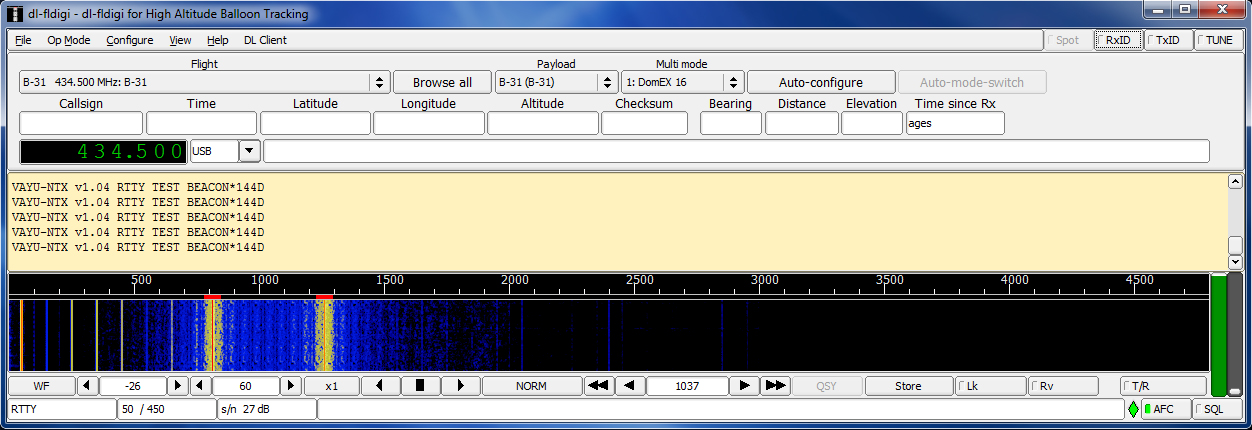
VAYU-NTX v1.04 RTTY Test
I will be continuing to update the PCB design whilst I get the code together. Another small improvement I have made is to add SMD pads for a smaller SMD crystal and flip LED2 round to be the same orientation as LED1. Why I placed it like that, I really don’t know. I have also added a marked jumper on the switch circuit to show the option to bypass the switch if required.
Now to interrogate the GPS module!