Before I regale you with the full VAYU-1 launch story, I would like to share with you a small success. If you are a regular reader of this blog, you will know that I took the original CHEAPO Tracker design by Chris Stubbs and modified it with a few additions that I wanted available for my future launches. This included designing a boost regulator to raise a 1.5V supply up to the board’s required 3.3V. I have been itching to try the circuit out and today I built it up. Just the boost regulator, since I figured that if that didn’t work, I would have to either modify the board or have a new design fabricated.

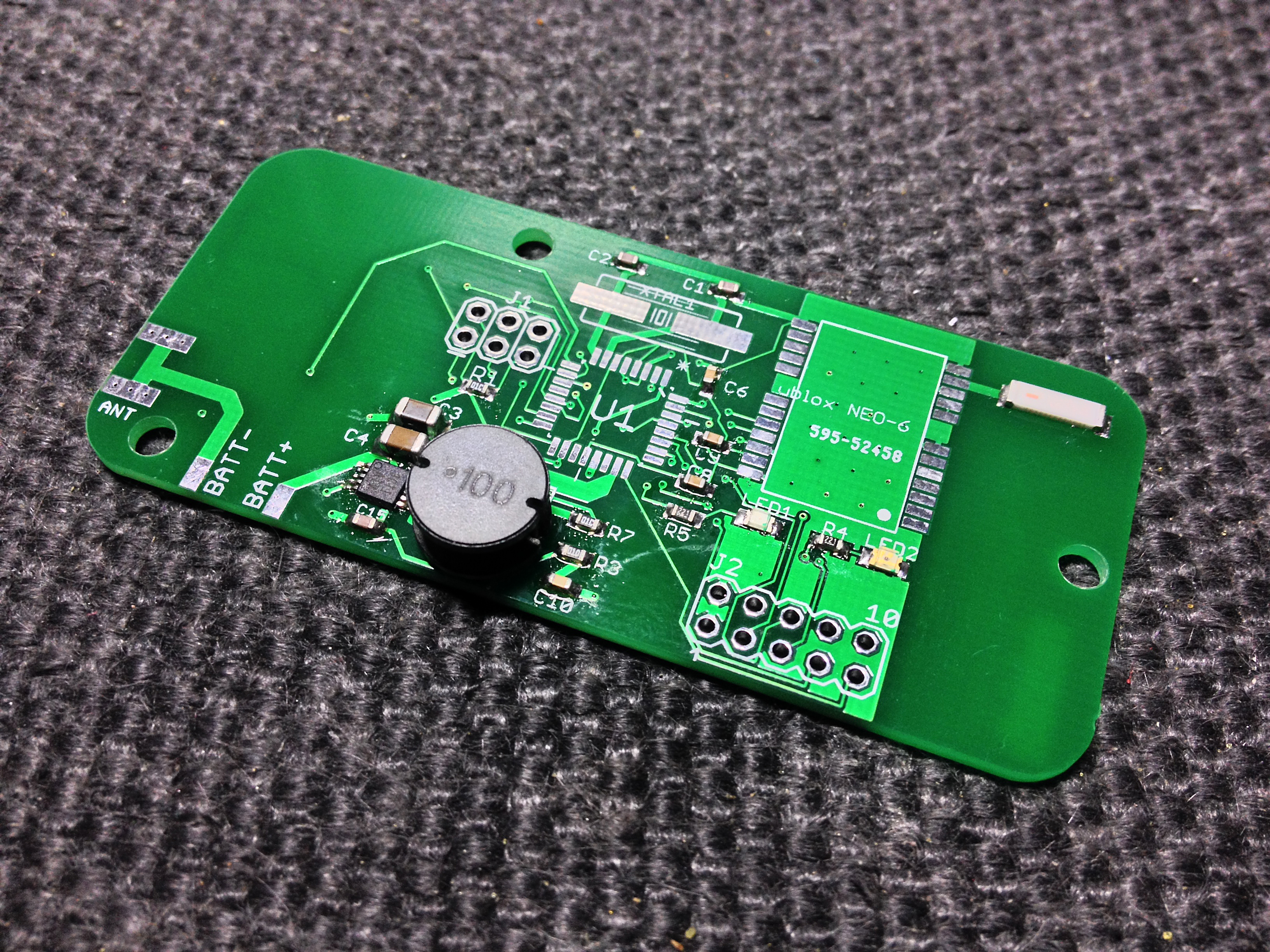
Vayu v1.01 pcb showing the built Boost Regulator

Vayu-1.01 Boost Regulator Close-up
This circuit was a real challenge to build. When soldering the TPS61016, there were two solder bridges created. I managed to remove one with a fine tipped soldering iron but the other wouldn’t budge until I got a sewing pin between the devices pins, heated it up and drew the excess solder out. I realise that I probably put too much solder paste on the contacts before heating with a hot air gun. I soldered the (rather large) coil next. This I did by placing a small amount of solder paste on the board, placing the coil in the correct place and blowing the hot air under the coil. I saw the solder melt which indicated it had affixed properly.
After soldering the final components of the regulator circuit, it was time to test it. I croc-clipped a couple of AA batteries in series to the power connections on the side of the board and took a reading with my DVM. 3.27V Close enough. I then tried with a single AA and got the same result. Perhaps one of the components is slightly out of tolerance but 3.27V is close enough not to matter in this instance. When I have a chance I’ll investigate the possibility of bringing it up to 3.3V exactly but modifying the surrounding components values.
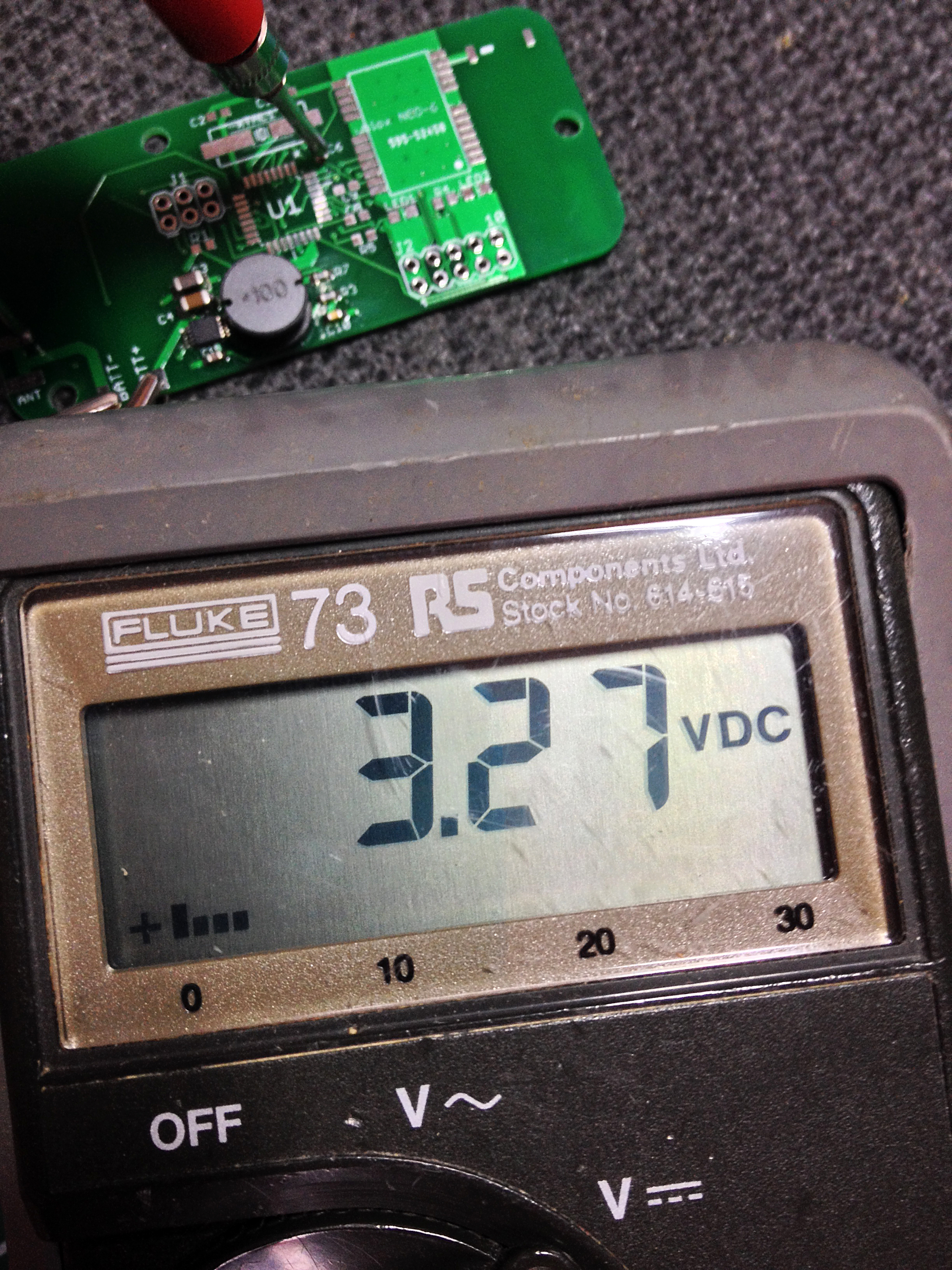
Vayu-1.01 Boost Regulator Meter Reading
The next step is to build the rest of the board when my order of ATMEGA328p-TQFP arrives. Having built the original CHEAPO board, I feel that I’ve had enough experience to make a good job of it. The real secret ingredient is patience. It takes a while to get each component placed correctly on the pads with solder paste. Also, if one ends up soldered incorrectly, it needs to be dealt with patiently and in an organised fashion.
I certainly couldn’t solder the TPS61016 with a conventional soldering iron, not even with the finest tip. I couldn’t see the contacts close enough to place the bit properly. I use a cheap hot air soldering station that I purchased on eBay along with solder paste.
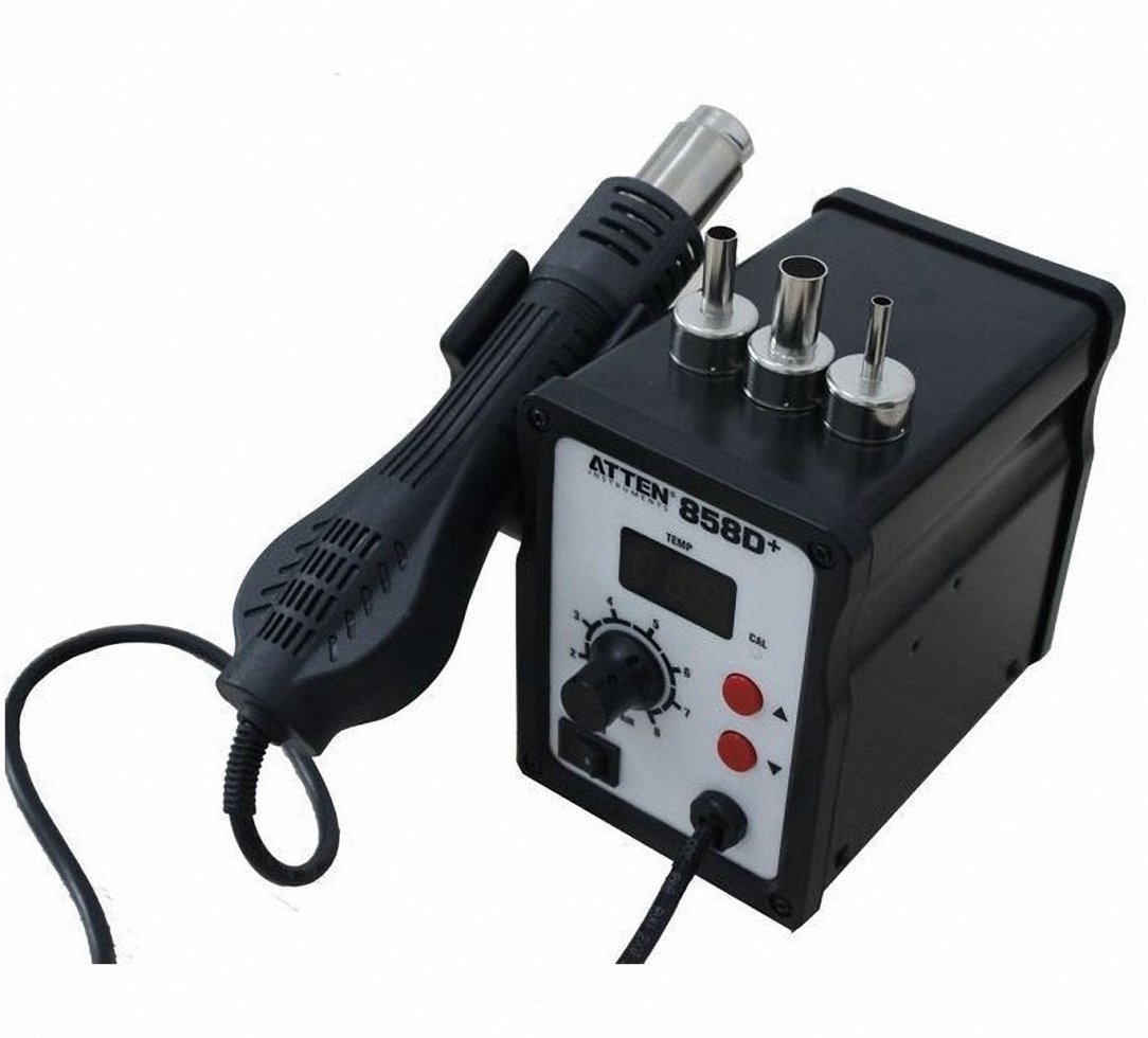
Atten 858D+ Hot Air Station
I have built several boards, all successful, with this method. I put a small amount of solder paste on the contacts on the PCB and tidy them up if necessary. I then place the component on the pads and orientate it properly. Then, I pass the hot air across the components pins and wait until the solder paste melts. Although the components and PCB get quite hot, I haven’t lost any yet.
Watch out for a further post of the completed build.
[UPDATE]
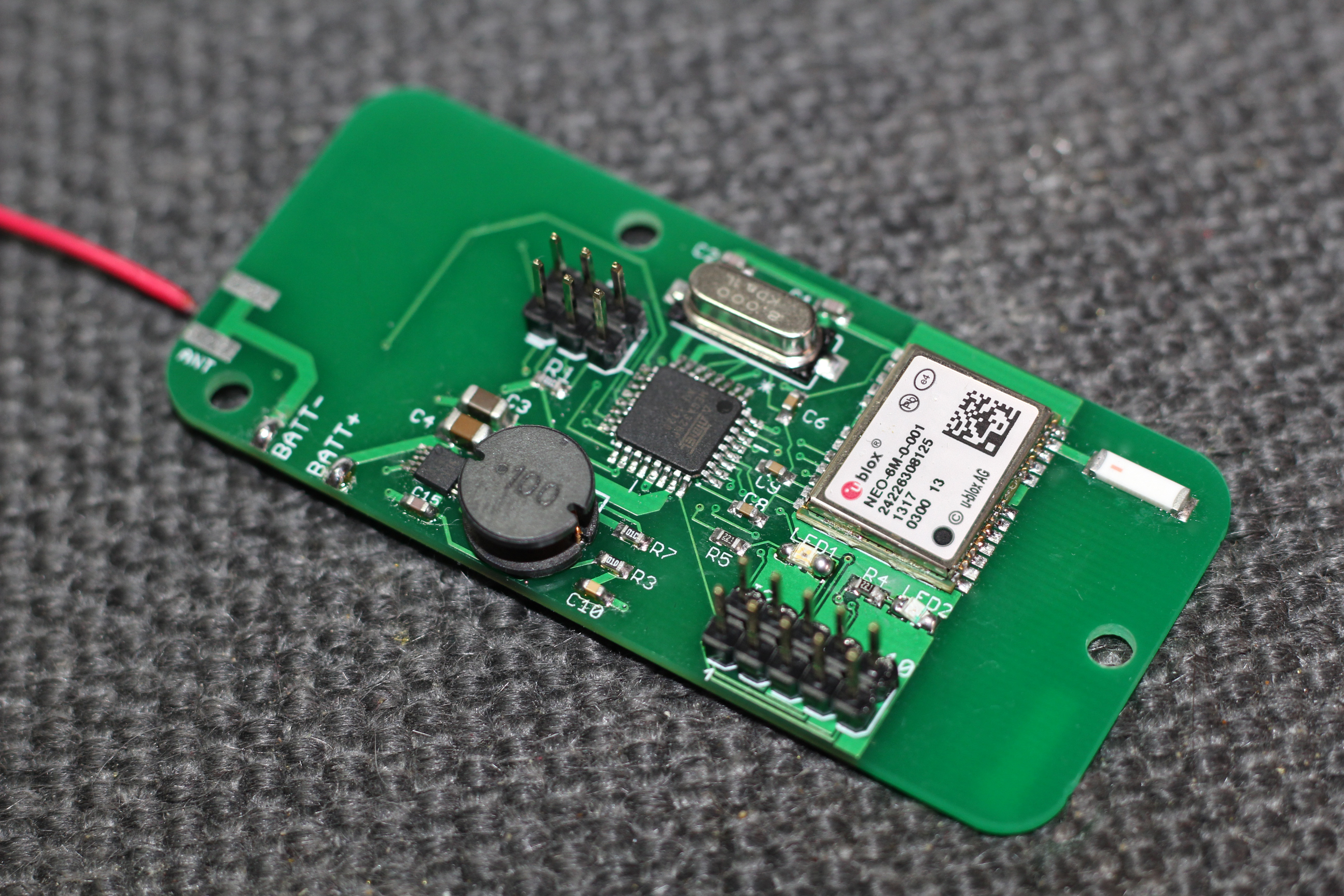
Since I had the components ready and the hot air station on standby, I thought I’d solder the rest of the small components on to the board in preparation of receiving the MCU. I left off the GPS unit, headers and crystal to give me enough room to solder the MCU properly.
VAYU v1.01 SMD Components
[UPDATE 2]
VAYU v1.01 Prototype fabricated by Hackvana
This is the fully finished, populated PCB. Challenging with all the many solder pads. Complete set of Docs available on the VAYU v1.02 page!
You must be logged in to post a comment.