Recovering Chris’s balloon and payload was great fun and as a thank you for doing so, he gave me an unpopulated circuit board of his HAB Tracker he called CHEAPO. I slightly modified this board under Chris’s direction to use an external boost regulator rather than the on board regulator. This allows the board to run on 2x AA Lithium Batteries. The boost regulator takes the 1.5V and raises it to 3.3V This is all very well but a little cumbersome having another circuit board connected. It is also a very inefficient design.
With this limitation in mind, I begun to wonder if I could re-design the circuit to have a built in boost regulator and maybe add a few other bells and whistles. After a bit of research, I came across the Texas Instruments TPS1006 device, which with a few other components, makes a nice efficient boost regulator. Upon reading the datasheet, I set about designing a layout based on Chris’s CHEAPO design. I removed the regulator circuit and replaced it with the boost regulator circuit. When I showed Chris, he kindly pointed out a few of my design blunders. I use Eagle for my circuit and circuit board design. Mainly because the base version is free. Although limited, it’s adequate for most hobby sized PCBs.
I had updated the design but meanwhile, I had found another Texas Instruments device that did the same job with fewer components, the TPS61016. I replaced the TPS1006 in the circuit and re-did the layout. Chris then pointed out that I hadn’t made the pads big enough for the current that would be drawn by the coil and capacitors in the boost regulator circuit and advised me to follow the datasheet more closely. It took me a few attempts but I finally managed to create a layout with regular connections and polygons placed on the board. I also tightened the component placement too.
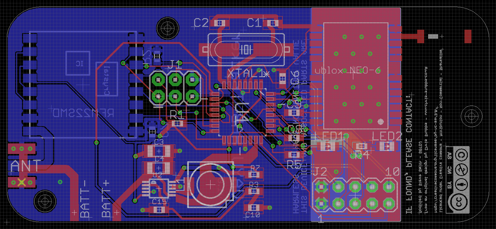
Almost finished, the VAYU layout in Eagle showing all layers.’
This will be a challenging board to make due to the minute connections on the SMD TPS61016. As well as adding the boost regulator to the board, I also removed the micro-SD Card socket, added 2 LEDs and a 10-way DIL connector which breaks out some of the ATMEGA328p I/O pins. On the rear I added an area in white for contact details to be written in permanent marker, indication that the board was made under a Creative Commons license with due credit to Chris for his original design and the name of the board, VAYU Version 1.0
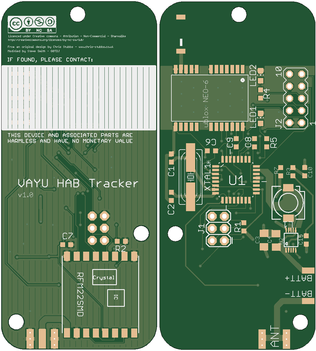
The board rendered on http://gerblook.org/ to check the Gerber files.
I will be using Hackvana to fabricate the boards so I used both their DRU (Design Rules) and CAM (Computer Aided Manufacturing) files. The DRU file indicates Hackvana’s minimum design sizes and specifications. Within Eagle, it is a good idea to check as you go to avoid lots of work later. Once complete, the design is processed using the CAM file. This outputs a set of ‘Gerber’ files which tell the fabricator’s machines how to create the board. Hackvana make this easy by requesting you zip up all the files produced and send them.
This has been a great learning experience and I feel that I could now probably design my own board from scratch. I may well do this in the future. In the mean time, I am waiting for funds to get the board fabricated and to collect the components together to build it.
Many thanks to Chris who gave me lots of his time and pointed me in the right direction a number of times.
[UPDATE]
With a little help from Mitch at Hackvana, I have ordered some boards. Stay tuned for building and testing when they arrive.
You must be logged in to post a comment.