While I await components and other things, I thought I’d show a tracker and identify the pieces. In my very limited experience of HAB, most trackers have common component parts so this one, designed by Chris Stubbs, probably takes ques from many other such devices.
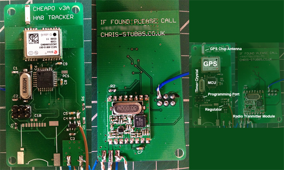
An image of Chris Stubbs’s HAB Tracker board CHEAPO – Labeled
This is the actual payload that I recovered for Chris on the 7th July 2013. Near the top of the double sided board on the top solder side is the GPS module. Made by uBlox, this appears to be the most popular of the GPS modules. Just above it, is the vey small chip antenna. Amazingly, this antenna works extremely well. Under the GPS module is the MCU (Micro Controller Unit). In this case it is an Atmega 328p in a TQFP surface mount package. To the left of it, the long silver shape marked 8.0000M is an 8MHz crystal which oscillates and is the clock that the whole device runs from. Just below these is a 6-pin DIL header to connect the programmer. Many programmers can be used to program the MCU but I use a BASP compatible type purchased from eBay for around £6.00GBP. To the right hand side of the circuit board near the brown wire is the regulator to maintain a constant voltage from the battery (not shown). On the rear of the board is mounted an RFM22b radio transmitter module.
This is a bit of a wizz-bang tour but the common components in any tracker board are the GPS to collect positional telemetry and supply the time, an MCU to collate the telemetry and add any other data required, such as the status of a switch, temperature or pressure readings. Or maybe you would like to have a teddy bear jump at a certain altitude. And finally a transmitter to send the telemetry to be received by stations on the ground.
You must be logged in to post a comment.